

Displays
Vehicle features and options
This chapter describes model-specific equip-
ment, systems, and functions that are currently
available, or may become available in the fu-
ture, even if they are not
present in the vehicle.
Additional information:
Vehicle equipment, refer to page
.
Live Vehicle
Principle
Live Vehicle is a virtual representation of your
vehicle with different information, e.g., vehicle
status or current driving
condition.
Corresponding information is shown on the
control display depending on the driving situa-
tion. Fault statuses are not taken into account.
Adaptive content or various static content can
be selected.
Adaptive content
The following content is displayed in alternat-
ing order and, if necessary, depending on the
selected drive mode:
▷
Vehicle status, refer to page
.
▷
Current driving condition, refer to page
.
▷
Sport displays, refer to page
▷
Efficiency trainer, refer to page
▷
.
▷
Depending on vehicle equipment: Terrain
View.
Static information
The following information may be shown per-
manently on the control display regardless of
the driving situation and driving mode set.
▷
Vehicle status.
▷
Trip data.
▷
Depending on vehicle equipment: Terrain
View.
Terrain View
Depending on vehicle equipment, the following
information is shown in Terrain View, for ex-
ample:
Icon
Description
Specified longitudinal inclina-
tion.
Specified lateral inclination.
Specified height for current po-
sition.
Self-leveling suspension.
Steering angle.
With all-wheel drive: distribu-
tion of drive torque to wheels.
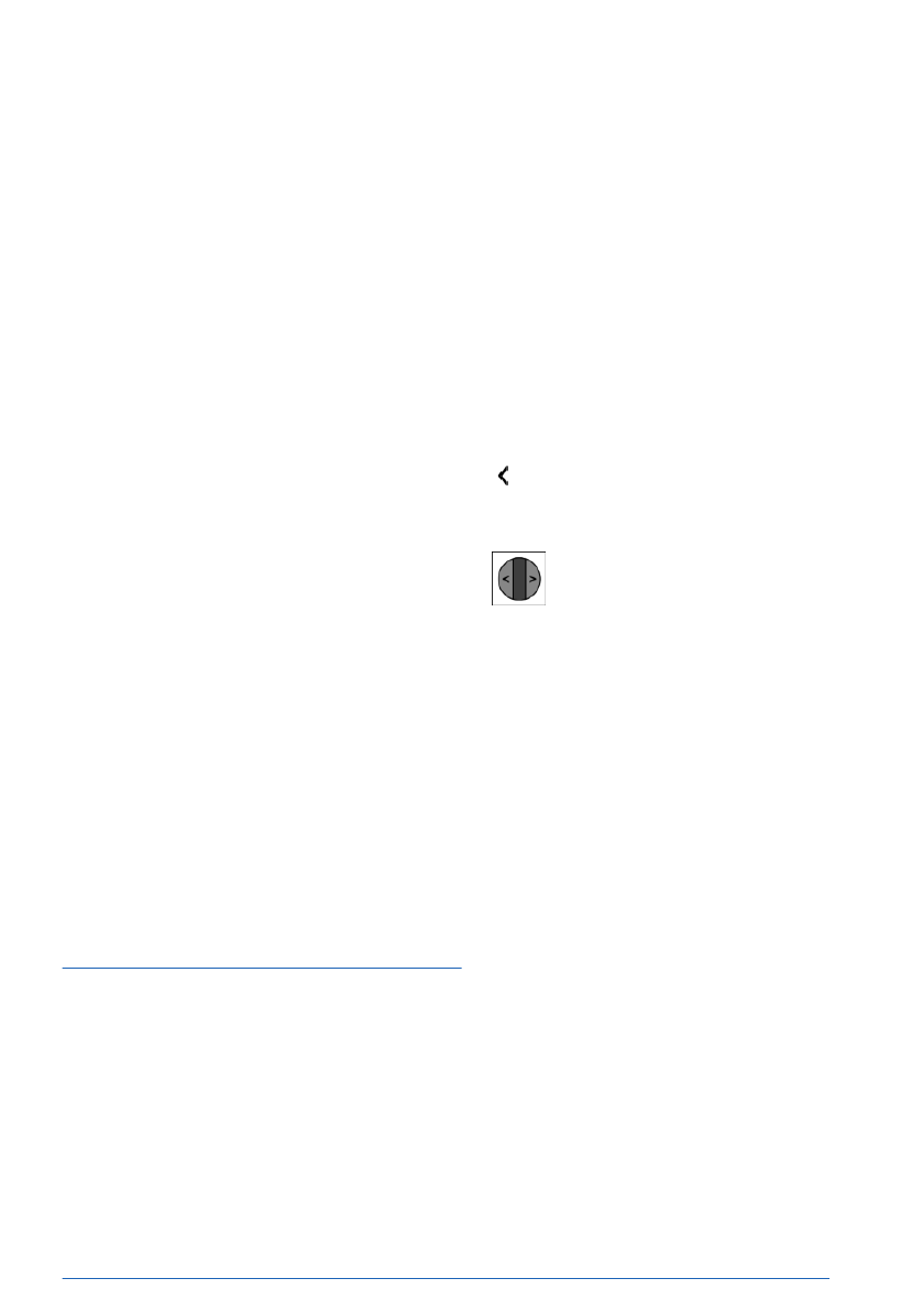
Adjusting the display
The Live Vehicle menu provides the option to
choose between adaptive or static content on
the left-hand side bar.
1.
To adjust the display, go through the menu
as follows: Apps menu / "Vehicle" / "Live
Vehicle".
2.
Select the desired setting.
BMW Head-up display
Principle
The Head-up display projects important infor-
mation in the driver's field of view, for instance
the speed. The driver can then view informa-
Displays
Controls
137
Online Edition
Depending on vehicle equipment, the height of
the Head-up display can be stored using the
memory function.
Visibility of the display
The visibility of the displays in the Head-up
display is influenced by the following factors:
▷
Seat position.
▷
Objects on the Head-up display's protective
glass.
▷
Dust or dirt on the Head-up display's pro-
tective glass.
▷
Windshield dirty on inside or outside.
▷
Sunglasses with certain polarization filters.
▷
Wet road.
▷
Unfavorable light conditions.
If the image is distorted, have the basic set-
tings checked by an authorized service center
or another qualified service center or repair
shop.
Special windshield
The special windshield is part of the Head-up
display system.
The
shape and coating of the special wind-
shield enable this system to
function.
If damaged, have the special windshield re-
placed by an authorized service center or an-
other qualified service center or repair shop.
Check Control
Principle
The Check Control system monitors functions
in the vehicle and notifies you of faults in the
monitored systems.
A
Check Control message is displayed as
a combination of indicator lights or warning
lights and text messages on the instrument
cluster and, if applicable, on the Head-up dis-
play. In addition, an acoustic signal may sound
and a text message may appear on the control
display.
Some Check
Control messages are hidden au-
tomatically after approx. 20 seconds, but they
will be stored. Stored Check Control messages
can be displayed on the control display. Urgent
Check Control messages are permanently dis-
played but may be hidden temporarily.
Hiding Check Control messages
Permanently displayed Check Control mes-
sages can be hidden temporarily. These mes-
sages are automatically displayed again after
approx. 8 seconds.
An arrow icon next to the Check Control
message indicates whether the Check Control
message can be hidden.
To hide Check Control messages, tilt
the thumbwheel on the steering wheel
to the left.
Displaying stored Check Control
messages
Saved Check Control messages and additional
information such as the cause of a fault or
the required action can be called up via Check
Control.
Depending on
the Check Control message, fur-
ther help can be selected.
1.
Go through the menu as follows: Apps
menu / "Vehicle" / "Vehicle status" / "Check
Control".
2.
Select the desired text message.
Display
A Check Control message is displayed in the
instrument cluster as a text message with an
icon.
For urgent
messages, an added text is auto-
matically displayed on the control display. If
several faults occur at once, the messages are
displayed consecutively.
Displays
Controls
139
Online Edition
cyclist, detected. Increased awareness is re-
quired.
Warning light
flashes and acoustic signal
sounds: risk of imminent collision with a per-
son, e.g., a pedestrian or cyclist, detected. Im-
mediately initiate braking or an evasive ma-
neuver.
Additional
information:
Warning function for pedestrians, refer to
.
Forward Collision Warning
Warning light illuminates: risk of colli-
sion, e.g., with a vehicle, detected. In-
creased awareness is required.
The warning light flashes and a signal sounds:
risk of imminent collision with a vehicle de-
tected. Immediately initiate braking or an eva-
sive
maneuver.
Additional information:
Warning function in rear-end collision situa-
.
Intersection Warning: vehicle detected from
the right
The warning light illuminates: risk of
collision with a vehicle crossing from
the right detected. Increased aware-
ness is required.
The
warning light flashes and a signal sounds:
risk of imminent collision with a crossing vehi-
cle detected. Immediately initiate braking or an
evasive
maneuver.
Additional information:
Warning function at intersections, refer to
.
Intersection Warning: vehicle detected from
the left
The warning light illuminates: risk of
collision with a vehicle crossing from
the left detected. Increased awareness is re-
quired.
The warning
light flashes and a signal sounds:
risk of imminent collision with a crossing vehi-
cle detected. Immediately initiate braking or an
evasive
maneuver.
Additional information:
Warning function at intersections, refer to
.
Distance Control
Warning light flashes and acoustic sig-
nal sounds: Brake and evade as neces-
sary.
Additional
information:
Distance Control, refer to page
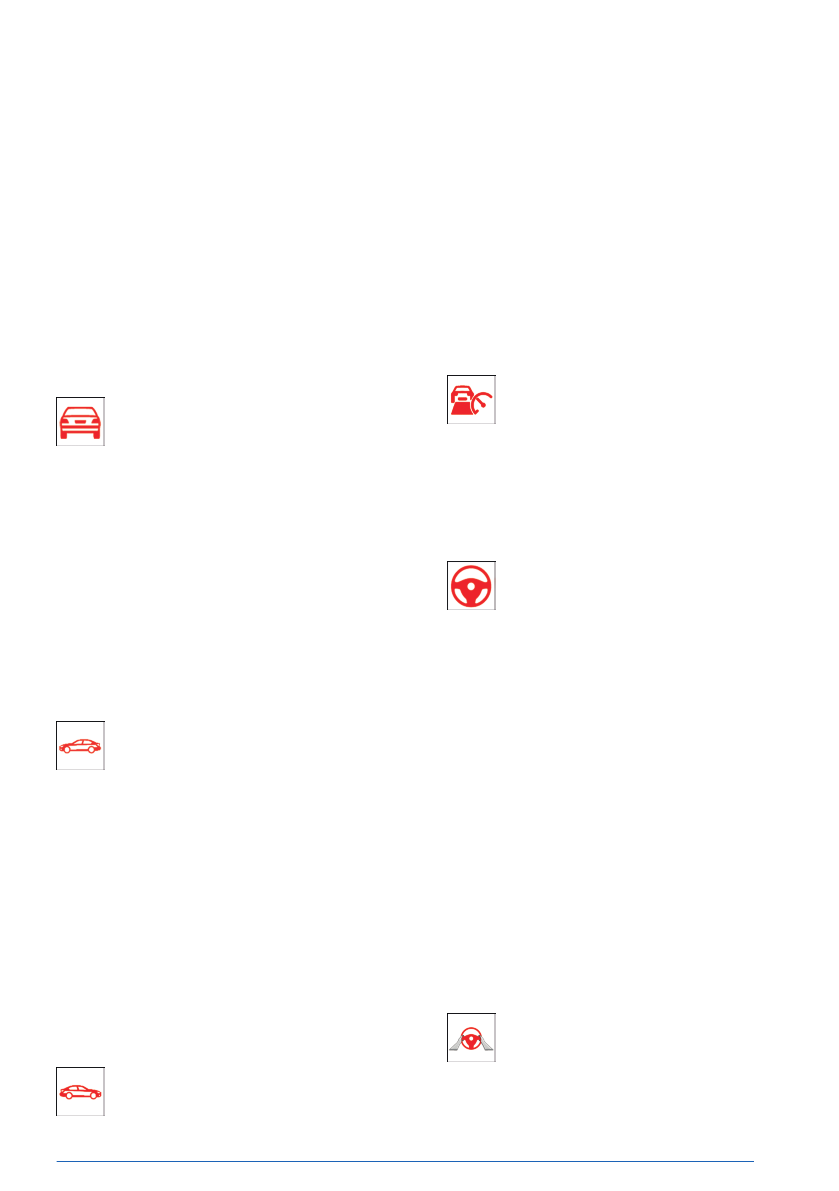
Assisted Driving Mode
Warning light flashes and acoustic sig-
nal sounds:
The system
is switched off or will be
interrupted very
soon.
Warning light illuminates and acoustic signal
sounds:
The driver's
line of sight is not directed at the
surrounding traffic. System interruption is im-
minent. The system reduces the speed to a
standstill if applicable. It is possible that the
system will not execute any supporting steer-
ing movements.
Keep an
eye on the surrounding traffic.
Additional information:
Assisted Driving Mode, refer to page
Assisted Driving Mode: The driver’s hands
are not currently gripping the steering wheel
Warning light illuminates and acoustic
signal sounds:
The
driver’s hands are not currently
gripping the steering wheel or, depending on
Displays
Controls
141
Online Edition
Flat tire monitor
Warning light illuminates: flat tire or tire
pressure loss has been
detected.
Reduce your speed and stop cau-
tiously. Avoid sudden braking and steering
maneuvers.
Additional
information:
Flat tire monitor, refer to page
.
Tire Pressure Monitor
Warning light illuminates: flat tire or tire
pressure loss has been detected. Fol-
low the information in the Check Con-
trol message.
Warning
light flashes then illuminates continu-
ously: flat tires or tire pressure losses cannot
be detected.
▷
Fault caused by systems or devices with
the same radio frequency: after leaving the
area of the interference, the system auto-
matically becomes active again.
▷
In the case of tires with special appro-
val: the Tire Pressure Monitor was unable
to complete the reset. Reset the system
again.
▷
Wheel without wheel electronics installed:
have it checked by an authorized service
center or another qualified service center or
repair shop as needed.
▷
Malfunction: have the vehicle checked by
an authorized service center or another
qualified service center or repair shop.
Additional
information:
Tire Pressure Monitor, refer to page
Steering system
The steering system may not be op-
erational.
Have the
vehicle checked by an author-
ized service center or another qualified service
center or repair shop.
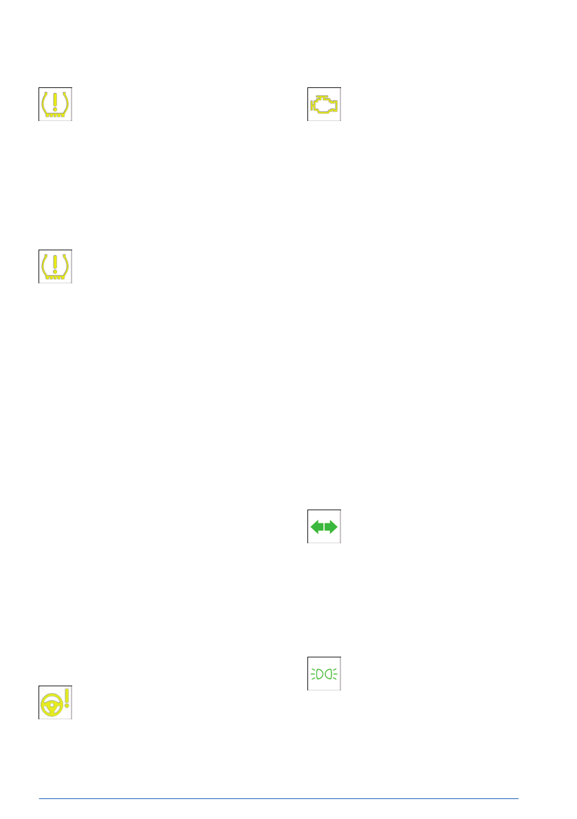
Pollutant emissions
▷
The warning light
illuminates:
The exhaust gas quality is declining,
e.g., because the fuel filler cap is fit-
ted incorrectly.
▷
The warning light flashes under certain cir-
cumstances:
This
indicates that there is excessive misfir-
ing in the
engine.
Reduce the vehicle speed and have the
system checked immediately by an author-
ized service center or another qualified
service center or repair shop. Otherwise,
severe engine misfires will very quickly
cause serious damage to emissions-related
components, especially the catalytic con-
verter.
Have the vehicle checked by an authorized
service center or another qualified service cen-
ter or repair
shop.
Additional information:
Diagnostic socket, refer to page
.
Green lights
Turn signal
The turn signal is turned
on.
If the indicator light is flashing unusu-
ally fast, this indicates that a turn signal
bulb has
failed.
Additional information:
Turn signal, refer to page
.
Parking lights
The parking lights are
turned on.
Additional information:
Parking lights, low-beam headlights,
refer to page
Displays
Controls
143
Online Edition
Lane Change Assistant: lane change in prog-
ress
Arrow icon for lane change green: the
system carries out a lane
change.
Additional information:
Lane Change Assistant, refer to page
.
Lane Change Assistant: lane change not pos-
sible
Gray line for lane boundary on cor-
responding side: the system has de-
tected a desire to change lanes. It is
not currently possible to
change lanes.
Additional information:
Lane Change Assistant, refer to
page
.
Assisted Driving Mode Plus
The system is
active.
Additional information:
Assisted Driving Mode Plus, refer to
.
Blue lights
High-beam headlights
High-beam headlights have been
turned on.
Additional
information:
High-beam headlights, refer to page
Automatic High Beam Assistant
High-beam headlights have been
turned on by the High Beam
Assistant.
Additional information:
High Beam Assistant, refer to page
Gray lights
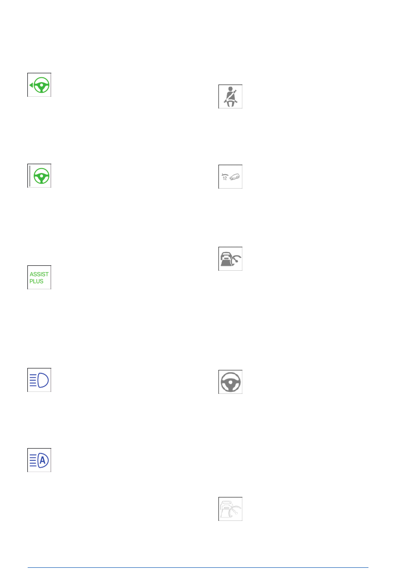
Seat belt reminder
Seat belt on the passenger seat or an-
other seat in the vehicle is
not buckled.
Additional information:
Seat belts, refer to page
.
Hill Descent Control is in standby
The system is in standby mode or tem-
porarily deactivated.
Additional
information:
Hill Descent Control, refer to page
.
Distance Control
Indicator light flashes: the requirements
to operate the system have not been
met. The system was deactivated but
applies the brakes until you actively resume
control by pressing on the brake pedal or ac-
celerator
pedal.
Additional information:
Distance Control, refer to page
Assisted Driving Mode
The system is on standby and does not
manipulate steering
movements.
System activates automatically as soon
as all function conditions
are fulfilled.
Additional information:
Assisted Driving Mode, refer to page
White lights
Cruise Control with Distance Control
No Distance Control because accelera-
tor pedal is being
pressed.
Additional information:
Displays
Controls
145
Online Edition

Example Description
In continuous manual
mode M:
Optimal gear is engaged.
With shift paddles: temporary
manual mode.
With shift paddles: Sport program.
Without shift paddles: LOW mode.
Shift information.
Additional
information:
Shift paddles, refer to page
Power gauge
Principle
The power gauge indicates the currently
drawn drive power as a percentage.
Enabling/disabling the power gauge
The power gauge or the tachometer is dis-
played depending on the selected drive mode
or the individually configured layout.
Display
Indicator for energy recovered, e.g., when de-
celerating, CHARGE,
arrow 1.
Drive power in percent, POWER, arrow 2.
Reduced drive power
The available drive power may be reduced due
to certain factors. The power gauge is adjusted
automatically.
In
addition, the icons on the power gauge and
tachometer indicate that the drive power is re-
duced.
Icon
Description
Blue icon: cold
drivetrain.
White icon: increased drive sys-
tem temperature, for instance
due to sustained or high
power demand when driving
on mountain roads.
Depending on vehicle equip-
ment and national-market ver-
sion:
Drive power
limitation defined
via the BMW Digital Key.
System-related functional limi-
tation.
A Check Control
message is
displayed in addition where ap-
plicable.
Displays
Controls
147
Online Edition
Display
Next to the fuel gauge on the
instrument cluster, the arrow be-
side the fuel pump symbol indi-
cates which side of the vehicle
the fuel filler flap is on.
The current range is displayed as numerical
value.
Fuel gauge
The current fill level of the fuel tank is dis-
played.
Vehicle
inclination may cause the display to
vary.
An arrow next to
the fuel pump icon in the
instrument cluster indicates the vehicle side on
which the fuel filler flap is
located.
Additional information:
Refueling, refer to page
.
Indicator light in the instrument cluster
The yellow indicator light illuminates,
once the fuel reserve is reached.
Engine temperature
The engine temperature is displayed in the in-
strument cluster.
▷
If the engine is cold, the nee-
dle is in the blue temperature
range, close to the limit po-
sition of the temperature dis-
play. WARM-UP is also dis-
played.
Drive at moderate RPM and
vehicle speeds.
▷
At normal operating temperature, the nee-
dle is in the middle or in the left half of the
temperature display.
▷
If the engine is hot, the needle is in the
red temperature range. In addition, a Check
Control message is displayed.
Additional
information:
Coolant level, refer to page
Display
The engine temperature is displayed in the in-
strument cluster.
▷
If the engine is cold, the nee-
dle is in the blue temperature
range, close to the left-hand
limit position of the temper-
ature display. WARM-UP is
also displayed.
Drive
at moderate RPM and
vehicle speeds.
▷
At normal operating temperature, the nee-
dle is in the middle or in the left half of the
temperature display.
▷
If the engine is hot, the needle is in the
red temperature range. In addition, a Check
Control message is displayed.
Additional
information:
Coolant level, refer to page
Indicator light in the instrument
cluster
A red indicator light is displayed.
Displays
Controls
149
Online Edition
Head-up display, refer to page
Owner's Manual for Navigation, Entertain-
ment, and Communication, refer to page
Configuring the central display
range
The content of the central display range on the
instrument cluster can be configured individu-
ally, for instance the trip data display.
1.
Press the Settings button on the
steering wheel.
A menu
bar is displayed in the instrument
cluster.
2.
"CONTENT"
Select
the menu by tilting the thumbwheel
on the steering wheel where applicable.
3.
Select the desired setting using the thumb-
wheel on the steering wheel.
Trip data
Principle
The trip data display provides various informa-
tion about the trip, e.g., average consumption
or trip distance.
The
trip data can be displayed on the control
display and in the instrument
cluster.
Depending on the setting in the Live Vehicle
menu, the trip data is shown on the control
display.
The values can
be displayed and reset de-
pending on different intervals.
Display on the control display
Displayable content
The following trip data is shown on the control
display:
▷
Configured interval for trip data displays.
▷
The average fuel consumption depend-
ing on the configured interval.
▷
The travel time according to the set in-
terval.
▷
The distance traveled depending on the
configured interval.
▷
Depending on the vehicle equipment:
the distance traveled in coasting mode.
Displaying trip data continuously
To display trip data permanently, go through
the menu as follows: Apps menu / "Vehicle" /
"Live Vehicle" / "Adaptive content" / "Trip
data".
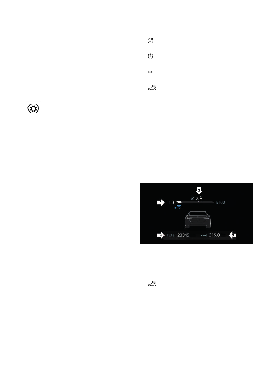
Display in the instrument cluster
Information on consumption and distance cov-
ered can be displayed in the instrument cluster
display.
▷
Current consumption, arrow 1.
▷
Average consumption, arrow 2.
▷
Distance traveled depending on the config-
ured interval, arrow 3.
Depending on vehicle equipment: an
icon appears while coasting.
▷
Total mileage, arrow 4.
Current consumption
The current fuel consumption display allows
you to check the current fuel consumption, e.g.,
to drive economically and in an environmen-
tally-friendly manner.
Displays
Controls
151
Online Edition
To configure the temporary display, go through
the menu as follows: Apps menu / "All" /
"Displays" / "Instrument cluster" / "Assisted
Driving info will appear in front of other
content"
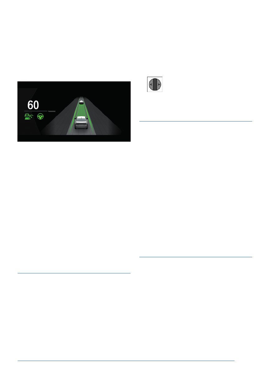
Display
An example of active Driver Assistance: the
indicator and warning lights for Distance Con-
trol and Assisted Driving Mode are displayed.
At the same time, the Distance Control is ani-
mated in Assisted View.
System limits
The detection capability of the Assisted View
system is limited.
Only
objects that are detected by the system
are taken into
account.
Additional information:
▷
Cameras, refer to page
▷
.
G-Meter
Principle
The G-Meter indicates the forces in the longi-
tudinal and transverse direction to which the
vehicle occupants are
subjected while driving.
The display can be configured on the central
display range of the
instrument cluster.
The values are automatically reset whenever
you start a new drive.
Additional
information:
Central display area, refer to page
.
Manually reseting G-Meter values
1.
Press the thumbwheel to display the G-Me-
ter on the instrument cluster.
2.
Press and hold the thumbwheel on
the steering wheel until the values reset.
Time and date
Various settings can be configured for display-
ing the date and
time.
Depending on vehicle equipment and national-
market version, the time zone can be set man-
ually or automatically. Automatic time zone ad-
justment automatically updates the time, the
date, and the time zone as necessary.
1.
Go through the menu as follows: Apps
menu / "Vehicle" / "System settings" /
"Time".
The
date is set automatically based on the
time zone.
2.
Select the desired setting.
Setting the units of meas-
urement
Depending on the national-market version, you
can set the units of measurement for some
values, for instance consumption, distances,
and temperature.
1.
Go through the menu as follows: Apps
menu / "Vehicle" / "System settings" /
"Units".
2.
Select the desired setting.
Displays
Controls
153
Online Edition

Service
Principle
The service notifications indicate recom-
mended maintenance
work.
After turning on drive-ready state, the instru-
ment cluster briefly displays the next service
appointment or the distance remaining until
the next recommended maintenance meas-
ures.
These can be read
out from the vehicle key at
an authorized service center.
Display
More information may be displayed on the
control display.
1.
Go through the menu as follows: Apps
menu / "Vehicle" / "Vehicle status" /
"Service".
Maintenance work as well as possible le-
gally mandated inspections are displayed.
2.
Select the desired entry to bring up more
information.
Entering appointment dates
The dates for mandatory vehicle inspections
can be entered.
Make
sure that the vehicle's date and time are
set correctly.
1.
Go through the menu as follows: Apps
menu / "Vehicle" / "Vehicle status" /
"Service" / "Vehicle inspection".
2.
Select the desired setting.
Displays
Controls
155
Online Edition
")


